


ALL-IN-ONE PLATFORM
esDynamic
Manage your attack workflows in a powerful and collaborative platform.
Expertise Modules
Executable catalog of attacks and techniques.
Infrastructure
Integrate your lab equipment and remotely manage your bench.
Lab equipments
Upgrade your lab with the latest hardware technologies.


PHYSICAL ATTACKS
Side Channel Attacks
Evaluate cryptography algorithms from data acquitition to result visualisation.
Fault Injection Attacks
Laser, Electromagnetic or Glitch to exploit a physical disruption.
Security Failure Analysis
Explore photoemission and thermal laser stimulation techniques.


EXPERTISE SERVICES
Evaluation Lab
Our team is ready to provide expert analysis of your hardware.
Starter Kits
Build know-how via built-in use cases developed on modern chips.
Cybersecurity Training
Grow expertise with hands-on training modules guided by a coach.


ALL-IN-ONE PLATFORM
esReverse
Static, dynamic and stress testing in a powerful and collaborative platform.
Extension: Intel x86, x64
Dynamic analyses for x86/x64 binaries with dedicated emulation frameworks.
Extension: ARM 32, 64
Dynamic analyses for ARM binaries with dedicated emulation frameworks.
DIFFERENT USAGES
Penetration Testing
Identify and exploit system vulnerabilities in a single platform.
Vulnerability Research
Uncover and address security gaps faster and more efficiently.
Malevolent Code Analysis
Effectively detect and neutralise harmful software.
Digital Forensics
Collaboratively analyse data to ensure thorough investigation.


EXPERTISE SERVICES
Software Assessment
Our team is ready to provide expert analysis of your binary code.
Cybersecurity training
Grow expertise with hands-on training modules guided by a coach.

INDUSTRIES
Semiconductor
Security Labs
Governmental agencies
Academics

ABOUT US
Why eShard?
Our team
Careers


FOLLOW US
Linkedin
Twitter
Youtube
Gitlab
Github


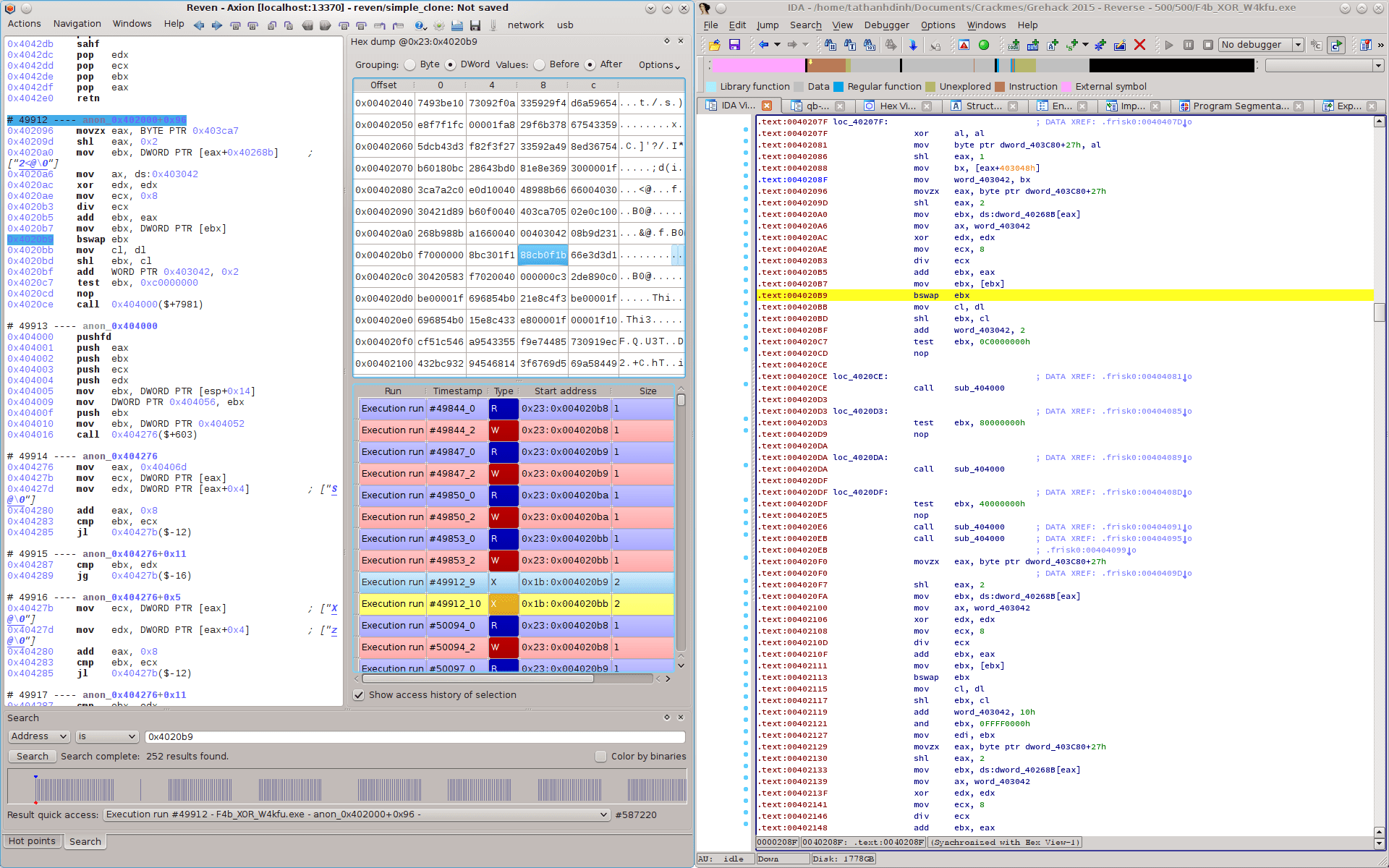
Unfolding obfuscated code with esReven (part 1, full write-up)


In this article, we present a reverse engineering task performed using esReven. The binary examined here is F4b_XOR_W4kfu, the challenge scoring the highest number of points over all categories (cryptography, exploit, reverse engineering, etc.) in Grehack 2015’s CTF. The binary is heavily obfuscated and the obfuscation techniques implemented are novel and interesting.
This is the first part in a series where we introduce our ongoing work in developing an automated code deobfuscation tool using esReven’s dynamic binary analysis framework. Since our approach is operational (i.e. we still require information about how the obfuscation techniques are implemented), the article is reserved for technical details of the challenge. We try our best to present, without skipping any detail, not only “how” the binary works but also “why” it is implemented that way. This question is sometimes the most important since it is where we can learn something from the author.
Remark: Most approaches in binary code deobfuscation are operational. Fully denotational approaches work in very strict cases only. As a direct consequence of Rice’s theorem, learning the behavior of general programs simply from input/output relations is a well-known undecidable problem. Even for much more restricted contexts, static analysis is NP-hard for smartly obfuscated programs. Recent semantics-based approaches are intrinsically operational. Though some approaches are considered generic, they work only on simple cases of very specific obfuscation techniques. However, special classes of loop-free programs can be efficiently synthesized from input/output with helps of SMT solvers.
Though we used esReven to solve this challenge, our method is absolutely not the unique attack.
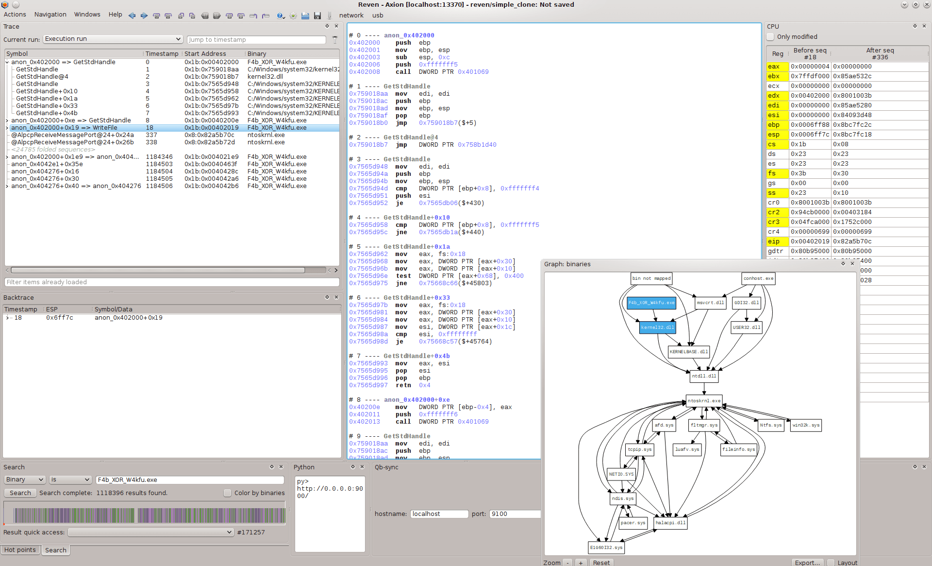
esReven - a very short introduction
Basically, esReven Axion is a system-level execution engine, enriched by code analysis plugins interacting with the core over Python or C/C++ API. One of the essential differences between esReven and other engines is that it performs execution for all execution threads presenting on the system, from ring 0 to ring 3.
In a basic reversing engineering task with esReven, we start by creating a scenario which executes the considered binary in a virtual machine; the result of the scenario will be used in further analysis. For example, in the case of F4b_XOR_W4kfu, we create a scenario which executes the binary with some input flag. The scenario terminates when the binary stops.
An advantage of esReven is that it computes all instructions being executed, instead of running them on real hardware. Hence, it is virtually immune (a.k.a until someone finds out bugs :-)) from anti-debugging/instrumenting tricks.
Remark: The approach of esReven is different from debuggers and dynamic binary instrumentation tools where instructions are still executed on the real hardware. This is a rich source for escaping tricks which exploit nontransparent effects of DBI.
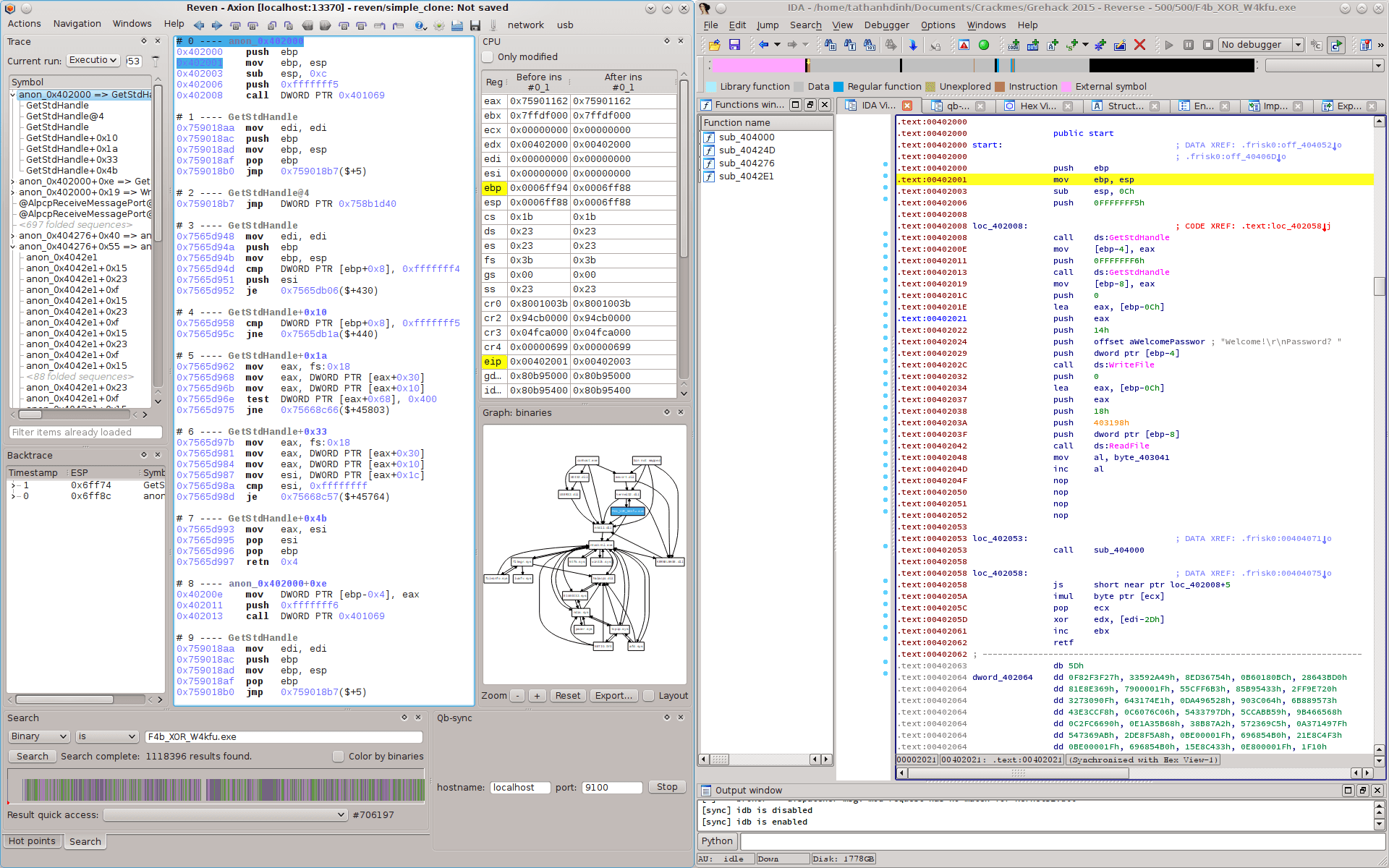
Synchronization with IDA Pro: esReven is designed to be a dynamic analysis tool. To benefit from advanced static analysis features (static binary view, disassembly/decompilation, data/control flow analysis, type propagation, etc.), Reven can synchronize with IDA Pro (as a “de-facto” reverse code engineering tool) using qb-sync.
That is enough for self-promoting words :), it’s time to get our hands dirty.
Introduction
F4b_XOR_W4kfu.exe is a 32-bit PE binary, without any fancy GUI. It asks for a password from the standard input and then prints Nop! or Yes!. The mission is to find out the good password (one that makes the program print Yes!).
./F4b_XOR_W4kfu.exe
Welcome!
Password? 1234aqzert
Nop!
The program uses several obfuscation techniques to prevent itself from being analyzed. First, its execution traces are extremely long, taking into consideration the fact that the program is just a CTF challenge. After receiving the input, Reven shows that there are 2.716.465.511 instructions executed until the first comparison of the password checking procedure \o/. We’ll see that this has to do with a code decryption/re-encryption mechanism and a nested multiprocess virtual machine execution model.
Second, the “input related” instructions are not local, but spread out in the trace, and are hard to be sliced. That makes it difficult to figure out how the password is manipulated and checked. Moreover the password checking algorithm is “mostly” constant time.
Last but not least, most instructions of the binary are encrypted: they are decrypted just before execution and are encrypted right after. So we cannot unpack it in the classical sense. The code formal approximation using phase semantics should work but its result is also trivial: the fixed-point is too coarse to be analyzed. More practical attacks based on code phases or waves cannot apply since they require the code to be “stable” at some execution point. Recently, some authors classified such technique of code packing into type VI, the most sophisticated class of binary code packers.
These properties make direct dynamic/concolic/static analysis difficult. This binary is also a fine counterexample which invalidates hypothesis in current automated code deobfuscation methods. Low-hanging fruit approaches, such as a black-box attack on counting the number of executed instructions, do not seem feasible: more than 2.7 billion instructions must be passed before reaching the first “input sensitive” comparison :(.
Workaround
The binary has 4 sections, all marked as executable, writable and executable. The section .frisk0 seems only an ID of all GreHack’s binaries, so we are not surprised. The execution starts at 0x402000 which is also the entry point. No TLS callback trick is applied, as confirmed by both Reven and IDA.
The first instructions are quite simple. For example, the ones at 0x402008 and 0x402013 are calls to GetStdHandle. The program calls WriteFile at 0x40202c, and ReadFile at 0x402042. It prints the strings Welcome! and Password?, then reads from the standard input.
But this short easy reversing time reaches an end: from now on, easy code does not exist anymore >:)
Code overwriting
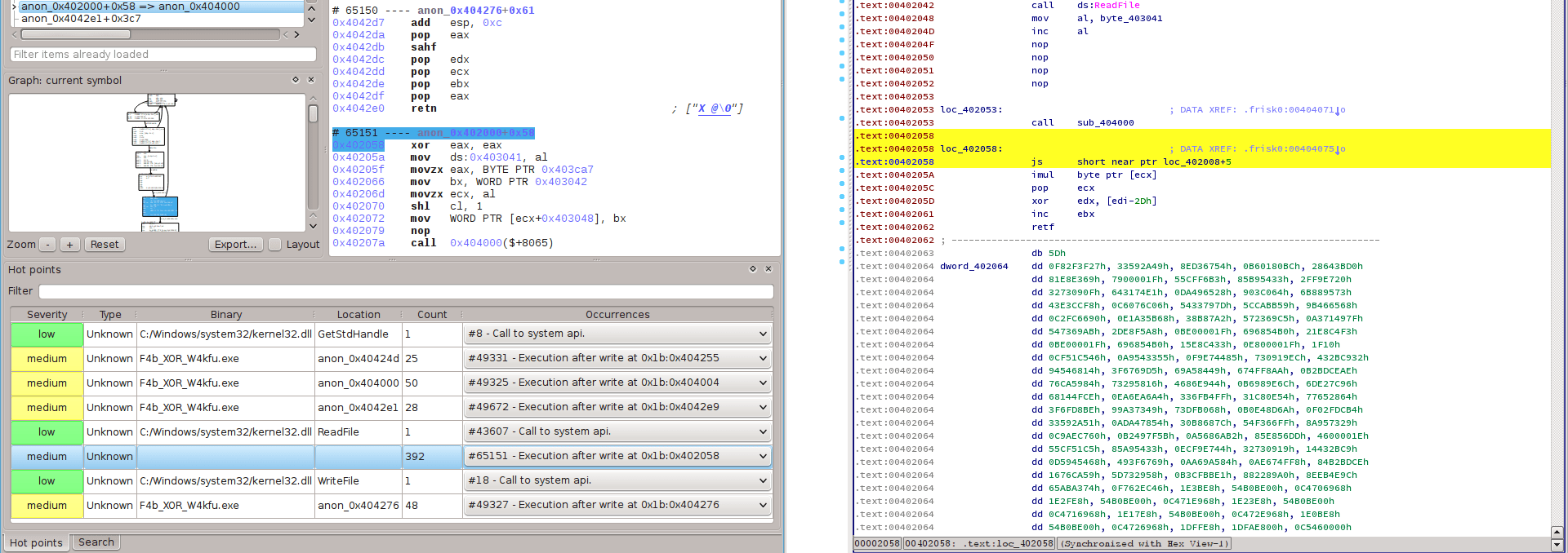
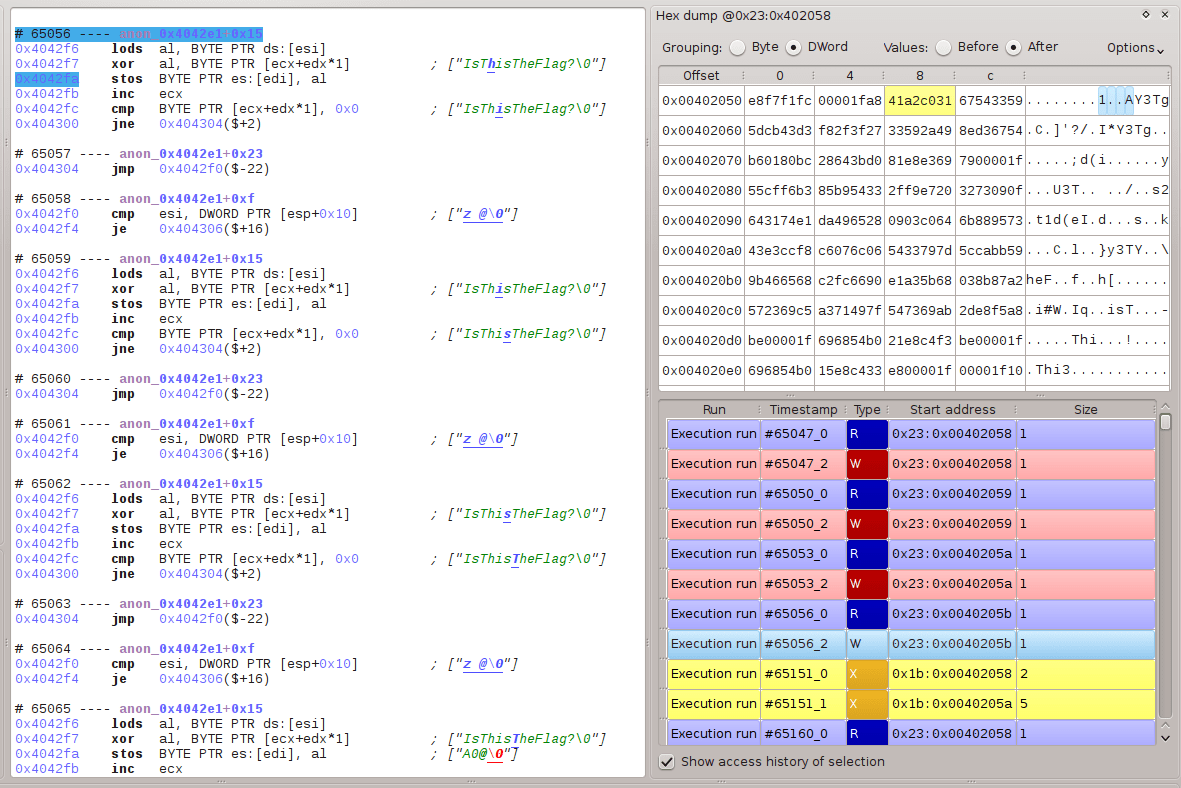
Passing statically over the simple previous instructions, the next instructions still look “normal”: some nop(s), then a call 0x40400. However, esReven notices that there are lots of execution after write (i.e. some memory addresses are overwritten before getting executed). Some of them are false positive due to the process mapping mechanism of ntoskrnl.exe, but the first one which really attracts our attention is at 0x402058: the instruction actually executed is xor eax, eax, instead of js 0x40200d as obtained out of the static disassembly.
Remark: esReven differs from DBI tools and debuggers since it works at the system level. Hence, it can trace the creation of a process (i.e. before the program gets run). In this process, instructions of the binary are written into the memory using some functions (e.g. MiCopyOnWrite) of ntoskrnl.exe, before execution. Consequently, such instructions are also analyzed by Reven as “execution after write”.
Following call 0x40400, something must have modified the instruction at 0x402058. Indeed, a backward dynamic tainting analysis by esReven shows a chain of read/write/execute on this address: the nearest instruction which writes this address is stosb at 0x4042fa.
Global control flow graph
We now know that the binary will modify some instructions before executing them. This can be revealed by examining the instructions following call 0x40400. But to quickly get an intuition of what is going on, we extract a partial control flow graph from the trace produced by Reven. The following graph is constructed from a trace of 10.000.000 instructions starting at 0x402048.
Partial control flow graph

(this is a vector image, click on it to observe the details)
Remark: The control flow graph provided by esReven is partial since it is constructed using the dynamic trace computed from the running program with a concrete input. But this is enough to probide valuable information about which kind of obfuscation we are dealing with.
Code virtualization
The form of the control flow graph suggests that it may be a virtual machine with switch-based dispatcher. The typical form of such a VM consists of a dispatcher which spreads over several basic blocks; and there exist many opcode handlers, each located in a “non trivial” basic block to which control flow is transferred from a much smaller number of “dispatch points”.
The basic blocks for opcode handlers are possibly, for example, the ones starting with the instructions at 0x402513, 0x40206a, 0x4025d, etc. The control flow transferred to all of them comes from the basic block ending at 0x4042e0, which may be the dispatch point of the dispatcher. Moreover, these basic blocks transfer the control flow to the same basic block starting at address 0x404000 (since they both end with call 0x404000), which may be the entry point of the dispatcher.
Remark: There are basic blocks, for example, at 0x4043a4, 0x404371, 0x40428c, etc. which come from (and reach) the same address; but they might not be opcode handlers since their semantics is trivial: most of them consists of just a simple unconditional direct jmp 0x40428.
Distinct instruction rate
Another criterion supporting the intuition about VM obfuscation is the number of distinct instructions over the total number of executed ones. Since the number of “virtual instructions” (of the VM) is normally much smaller than the number of the real hardware instructions (i.e.x86 ISA), we would observe that there are not “too much” distinct instructions in a binary obfuscated by a VM. The following diagram presents the number of distinct instructions over the trace length: there are only about 500 distinct instructions over a trace of length 10.000.000!!!

Remark: Such a form of control flow graph can be observed also in binaries obfuscated by VMProtect and some early versions of Code Virtualizer. In later versions, Code Virtualizer uses threaded code: the control flow to the next opcode’s handler is calculated at the end of the executing handler, then we cannot observe this form. In some ad-hoc VM obfuscated binaries, e.g. HyperUnpackMe2, the dispatcher has multiple dispatch points (there was a very nice writeup of this binary using IDA). The replacement of the switch by nested if commands gives a similar effect.
The patterns above then just give a hint to recognize the applied obfuscation technique. Without a thorough analysis, we cannot say that the binary is obfuscated by a VM. Indeed, the same patterns can be observed in programs which are not obfuscated at all, and conversely some program are VM obfuscated but these patterns are not directly visible. Finally, we do not give a formal definition for virtualization obfuscation yet :-), this problem is discussed in next articles.
Reversing the virtual machine
So we have an intuition that there exists possibly a VM whose dispatcher entry point starts at 0x404000, and single dispatch point ends at 0x4042e0. We reverse in detail the dispatcher now.
First phase
The dispatcher can be divided into “two phases” with “transition instructions” in between: the second phase strictly post-dominances the transition code, whereas the transition strictly post-dominances the first phase with the following control flow graph.

Return address table
As seen previously in the global CFG, the ret instruction at 0x40404e transfers the control flow to different basic blocks, but the continued instructions are not the ones following call 0x404000. The called function is then not a “standard” function which we normally observe in an Algol-like language: it does not return to the location where it was called. Hence, the return address must be modified somehow.
Return address modification: Looking at instructions at 0x404005 and 0x404009, we observe that the original return address is saved to memory at 0x404056, while a replacement return address overwrite the original address (instruction mov [esp + 0x14], eax at 0x404045). This new address is computed in a loop between 0x404030 and 0x40403b.
The semantics of the loop is simple: it consumes ebx which is the current return address (c.f. pop at 0x40402a as well as push at 0x40400f), and a list at address 0x404309. It looks for an entry in the list indexed with the current return address. When the entry is found, the new return address is updated by the transition code of the entry. The structure of this table is shown below.

Entries in this table are consecutive: the location of the next entry is calculated by adding the current entry’s address with the entry’s length. So once we know the starting address of the list, which is 0x404309, all entries can be completely located. Actually, the following algorithm calculates the new return address nextRet from the current one currentRet.
let retTable be the array of bytes at 0x404309
let mutable entryOffset = 0
while currentRet <> dword [retTable + entryOffset] do // find the corresponding entry
  let entryLength = retTable[entryOffset + 4]
  entryOffset <- entryOffset + entryLength
nextRet = dword [retTable + entryOffset + 10]
Address interval computation and encryption
We now notice for call(s) at 0x404016 and 0x404022, that the called functions are standard (i.e. they return back to the location following where they were called). These functions are strongly correlated, their semantics is simple but important.
Address interval computation: The first function consumes a dword at 0x404052 (through ebx), a table of dword(s) at 0x40406d; and return the first pair of two consecutive dword(s) in this table (through ecx and edx) satisfying ecx <= ebx <= edx. The algorithm implemented in this function is shown below.
let inTable be the array of dword(s) from 0x404052 to 0x40424d
let inEbx = dword [0x404052]
let loBounds, hiBounds = List.foldBack (fun addr (los,his) -> addr::his, los) inTable ([],[])
(outEcx,outEdx) = List.find (fun (lo,hi) -> (lo <= inEbx && inEbx <= hi)) <| List.zip loBounds hiBounds
Code interval encryption: The second consumes the output of the first one as an interval of addresses and the string IsThisTheFlag? (trust us, we have tried, and it is not the flag
), it simply xor this interval with this string in ECB mode.
Summary
Not everything is clear right now, but we have obtained some information. Concretely, the first phase has:
- backed up the original return address as a dword at 0x404056,
- calculated an interval of addresses using a dword stored at 0x404052, then
- xored the interval with the string IsThisTheFlag?,
- used the original return address to find an entry in the return address table, next
- calculated the address of the transition code of this entry, and
- replaced the original return address in the stack with the one of the transition code, then
- backed up the address of the entry as a dword at 0x40405a, finally
- used ret to transfer the control flow to the transition code.
Remark: At this point, we cannot yet “prove” the meaning of the address interval, neither the dword stored at 0x404052 (we will do this later). But honestly, using the global control flow graph, and dynamically checking with Reven how these addresses are used, we “already know” that each interval is possibly the bound of an opcode handler, the dword at 0x404052 stores nothing but the entry point of the last executed handler. This might be tricky
, but Reven is really helpful in suggesting what happened.
Transition code
Because of the effect of ret, the control flow is transferred to transition instructions located at the transition code. The addresses of transition code can be extracted easily using the structure of the return address table introduced above.
0x404313; 0x404322; 0x404331; 0x404344; 0x404353; 0x404362; 0x404371; 0x404380; 0x40438f; 0x4043a4;
0x4043b3; 0x4043c2; 0x4043d1; 0x4043e3; 0x4043f2; 0x404401; 0x404410; 0x40441f; 0x40442e; 0x40443d;
0x40444f; 0x40445e; 0x40446d; 0x40447c; 0x40448b; 0x40449a; 0x4044a9; 0x4044b8; 0x4044c7; 0x4044d6;
0x4044eb; 0x4044fa; 0x404509; 0x404518; 0x404527; 0x404536; 0x404545; 0x404554; 0x404563; 0x404579;
0x404588; 0x404597; 0x4045a6; 0x4045b5; 0x4045c4; 0x4045d6; 0x4045e5; 0x4045f4; 0x404603; 0x404612;
0x404621; 0x404630; 0x40463f; 0x40464e; 0x40465d; 0x40466c; 0x40467b; 0x40468a; 0x404699; 0x4046a8
We can also check these addresses in the global control flow graph above. All of them terminate with an unconditional direct jmp 0x40428c which transfers the control flow to the second phase of the dispatcher.
Second phase
The second phase of the dispatcher starts at address 0x40428c and terminates at 0x4042e0 (we know that since this is also the address of the single dispatch point that we have observed from the global control flow graph). This phase has the following control flow graph.

The second phase uses some tricks similar to those observed in the first one. The last instruction ret also diverts the control flow to different addresses. This is the effect of the instruction at 0x404208c (which reverses a stack space for the return address), and one at 0x4042c2 (which fills the return address). From the global control flow graph, each return address commences an opcode handler.
Inter-phase encryption/decryption relation
There are also two call(s), one at 0x4042c6 which calls the same function as 0x404016 in the first phase, and another at 0x4042d2 which calls a different function but exactly the same as one at 0x404022 (also in the first phase).
Remark: We still do not understand yet why the functions called at 0x404022 (in the first phase) and 0x4042d2 (in the second) are exactly the same; this is obviously a code redundancy. :-/
We recall that the address interval computation functions in the first phase consume a dword stored at 0x404052 to calculate an address interval, then xor this interval with IsThisTheFlag?. The functions in the second phase do exactly the same thing, except that they consume a dword either stored at 0x404056 (c.f. the instruction at 0x4042b6) or extracted from ecx+0x6 (c.f. the instruction at 0x40429d).
The first phase uses a dword at 0x404052. Now in the second phase, we know that this address is used to store the value consumed by the two functions (c.f. the instruction at 0x4042bc).
Code gadget encryption/decryption: So the pair of address interval functions called in both phases uses the same value to calculate an interval of addresses, then xor this interval with the string IsThisTheFlag?. The second phase then forwards the control flow to this xored code interval (since the control flow is forwarded to each code interval by a ret instruction, we call it a gadget. We also notice that xoring a gadget with the same string will restore the original data.
By running several scenarios in esReven with different inputs, we observe that the code modification happens only in the dispatcher, the gadgets do not interfere in this process. The gadget encryption/decryption mechanism of the dispatcher is pretty clear now, it is summarized in the following steps:
- the first phase computes the last executed gadget from the stored entry point, next
- encrypts this gadget (xor with IsThisTheFlag?).
- the second phase calculates the entry point of the next gadget, and
- uses this value to compute the next encrypted gadget, then
- decrypts this gadget (xor with IsThisTheFlag?), finally
- forwards the control flow to the entry point of the gadget.
Remark: one should distinguish a gadget entry point from an original return address. A gadget is an interval of addresses which is encrypted/decrypted as a whole. Its entry points are addresses for which there are some control flow coming from another gadget.
An original return address is naturally an entry point, but there are also entry points which are not an original return address. As we will present later, a gadget may have several entry points: an original return address is the first address of a gadget - it is called the natural entry point of the gadget.
Decrypting all code gadgets: we can decrypt all gadgets now. That leads also to statically decrypting all encrypted content of the binary. Indeed, given an original return address, we can compute the corresponding gadget, then decrypt the gadget by xoring it with the IsThisTheFlag? key. Moreover, all possible return addresses can be extracted by traversing the return address table: for each entry, extract its return address field. The list of all return addresses is:
0x402058; 0x40207f; 0x4020d3; 0x4020df; 0x4020eb; 0x4020f0; 0x40217b; 0x4021c5; 0x4021d1; 0x4021dd;
0x4021e9; 0x4021f5; 0x402201; 0x402206; 0x402250; 0x40227f; 0x4022c9; 0x4022f8; 0x40233a; 0x402346;
0x402352; 0x40235e; 0x40236a; 0x4023d4; 0x4023de; 0x402428; 0x402434; 0x402440; 0x402445; 0x402460;
0x402486; 0x4024c8; 0x4024cd; 0x402501; 0x40250d; 0x402513; 0x40254c; 0x402572; 0x40257c; 0x402582;
0x4025b4; 0x4025cf; 0x4025df; 0x4025f6; 0x40260a; 0x40263c; 0x40266e; 0x4026cc; 0x4026de; 0x4026ea;
0x40270f; 0x402721; 0x40272d; 0x402750; 0x402758; 0x40275f; 0x402766; 0x402772; 0x402779; 0x402780
and the map between a return address and the address interval of the corresponding gadget is:
0x402058 => [0x402058, 0x40207a]; 0x40207f => [0x40207f, 0x4020ce]; 0x4020d3 => [0x4020d3, 0x4020da];
0x4020df => [0x4020df, 0x4020e6]; 0x4020eb => [0x4020eb, 0x4020eb]; 0x4020f0 => [0x4020f0, 0x402176];
0x40217b => [0x40217b, 0x4021c0]; 0x4021c5 => [0x4021c5, 0x4021cc]; 0x4021d1 => [0x4021d1, 0x4021d8];
0x4021dd => [0x4021dd, 0x4021e4]; 0x4021e9 => [0x4021e9, 0x4021f0]; 0x4021f5 => [0x4021f5, 0x4021fc];
0x402201 => [0x402201, 0x402201]; 0x402206 => [0x402206, 0x40224b]; 0x402250 => [0x402250, 0x40227a];
0x40227f => [0x40227f, 0x4022c4]; 0x4022c9 => [0x4022c9, 0x4022f3]; 0x4022f8 => [0x4022f8, 0x402335];
0x40233a => [0x40233a, 0x402341]; 0x402346 => [0x402346, 0x40234d]; 0x402352 => [0x402352, 0x402359];
0x40235e => [0x40235e, 0x402365]; 0x40236a => [0x40236a, 0x4023cf]; 0x4023d4 => [0x4023d4, 0x4023d9];
0x4023de => [0x4023de, 0x402423]; 0x402428 => [0x402428, 0x40242f]; 0x402434 => [0x402434, 0x40243b];
0x402440 => [0x402440, 0x402440]; 0x402445 => [0x402445, 0x40245b]; 0x402460 => [0x402460, 0x402481];
0x402486 => [0x402486, 0x4024c3]; 0x4024c8 => [0x4024c8, 0x4024c8]; 0x4024cd => [0x4024cd, 0x4024fc];
0x402501 => [0x402501, 0x402508]; 0x40250d => [0x40250d, 0x40250e]; 0x402513 => [0x402513, 0x402547];
0x40254c => [0x40254c, 0x40256d]; 0x402572 => [0x402572, 0x402577]; 0x40257c => [0x40257c, 0x40257d];
0x402582 => [0x402582, 0x4025af]; 0x4025b4 => [0x4025b4, 0x4025ca]; 0x4025cf => [0x4025cf, 0x4025da];
0x4025df => [0x4025df, 0x4025f1]; 0x4025f6 => [0x4025f6, 0x402605]; 0x40260a => [0x40260a, 0x402637];
0x40263c => [0x40263c, 0x402669]; 0x40266e => [0x40266e, 0x4026c7]; 0x4026cc => [0x4026cc, 0x4026d9];
0x4026de => [0x4026de, 0x4026e5]; 0x4026ea => [0x4026ea, 0x40270a]; 0x40270f => [0x40270f, 0x40271c];
0x402721 => [0x402721, 0x402728]; 0x40272d => [0x40272d, 0x40274b]; 0x402750 => [0x402750, 0x402753];
0x402758 => [0x402758, 0x40275a]; 0x40275f => [0x40275f, 0x402761]; 0x402766 => [0x402766, 0x40276d];
0x402772 => [0x402772, 0x402774]; 0x402779 => [0x402779, 0x40277b]
Remark: One can use the following Python script to decrypt the binary. When synchronizing the IDA’s view with esReven (using the qb-sync plugin), one gets a familiar effect of debugging a program but without caring that it is encrypted B-)
def decryptInterval(loAddr, hiAddr):
    print 'decrypting gadget from 0x{0:x} to 0x{1:x}'.format(lo_addr, hi_addr)
    maskOffset = 0x40405e
    for addr in range(loAddr, hiAddr):
	    origByte = Byte(addr)
	    maskByte = Byte(maskOffset)
	    PatchByte(addr, origByte^maskByte)
	    maskOffset += 1
	    if (Byte(maskOffset) == 0):
	      maskOffset = 0x40405e

opcodeIntervals = [(0x402058, 0x40207a), (0x40207f, 0x4020ce), (0x4020d3, 0x4020da), (0x4020df, 0x4020e6),
                   (0x4020eb, 0x4020eb), (0x4020f0, 0x402176), (0x40217b, 0x4021c0), (0x4021c5, 0x4021cc),
                   (0x4021d1, 0x4021d8), (0x4021dd, 0x4021e4), (0x4021e9, 0x4021f0), (0x4021f5, 0x4021fc),
                   (0x402201, 0x402201), (0x402206, 0x40224b), (0x402250, 0x40227a), (0x40227f, 0x4022c4),
                   (0x4022c9, 0x4022f3), (0x4022f8, 0x402335), (0x40233a, 0x402341), (0x402346, 0x40234d),
                   (0x402352, 0x402359), (0x40235e, 0x402365), (0x40236a, 0x4023cf), (0x4023d4, 0x4023d9),
                   (0x4023de, 0x402423), (0x402428, 0x40242f), (0x402434, 0x40243b), (0x402440, 0x402440),
                   (0x402445, 0x40245b), (0x402460, 0x402481), (0x402486, 0x4024c3), (0x4024c8, 0x4024c8),
                   (0x4024cd, 0x4024fc), (0x402501, 0x402508), (0x40250d, 0x40250e), (0x402513, 0x402547),
                   (0x40254c, 0x40256d), (0x402572, 0x402577), (0x40257c, 0x40257d), (0x402582, 0x4025af),
                   (0x4025b4, 0x4025ca), (0x4025cf, 0x4025da), (0x4025df, 0x4025f1), (0x4025f6, 0x402605),
                   (0x40260a, 0x402637), (0x40263c, 0x402669), (0x40266e, 0x4026c7), (0x4026cc, 0x4026d9),
                   (0x4026de, 0x4026e5), (0x4026ea, 0x40270a), (0x40270f, 0x40271c), (0x402721, 0x402728),
                   (0x40272d, 0x40274b), (0x402750, 0x402753), (0x402758, 0x40275a), (0x40275f, 0x402761),
                   (0x402766, 0x40276d), (0x402772, 0x402774), (0x402779, 0x40277b)]

for loAddr, hiAddr in opcodeIntervals:
    decryptInterval(loAddr, hiAddr)
Next executed gadget address calculation
The return address of the second phase determines the address of the next executed gadget. It comes either from 0x404056 or [ecx+0x6] where ecx gets its value from 0x40405a (c.f. the instruction at 0x404293). In the first phase, the dword at 0x404056 has been used to store the original return address, whereas 0x40405a has been used to store the address of an entry in the return address table. This entry’s address is calculated, as described below, from the original return address.
Return address table in detail: the instructions at 0x404293, 0x404299 and 0x40429d reveal how an entry of the return address table is parsed in the second phase. There is a 1-byte field at offset 5 which is used later to compute the ZF flag (c.f. the instruction at 0x4042b4), and a dword field at offset 6 which is used as a candidate for the next gadget address.
In the first phase, we observed that each entry consists of 10 bytes plus the transition code. The first part of thz 10 bytes consists in a dword for the return address, and 1 byte for the entry length. The analysis above discloses the next part of the 10 bytes. Hence, the detailed structure of the return address table is shown below.

Opaque predicate: there is a conditional jump at 0x4042a1 but Reven detects that the condition never holds. That means edx, which is the flag value of an entry, is never equal to 0. Indeed, we can easily extract the flag values of all entries in this table, they are:
19; 29; 19; 19; 29; 19; 28; 19; 29; 19; 19; 19; 29; 19; 19; 29; 19; 19; 29; 28; 19; 29; 19; 19;
29; 29; 29; 29; 28; 29; 19; 19; 28; 19; 29; 29; 29; 28; 28; 29; 29; 29; 16; 28; 29; 19; 29; 19;
29; 19; 19; 19; 29; 28; 19; 19; 19; 29; 29; 17
Flag extraction: the address of the next gadget depends on whether the condition jump at 0x4042b4 holds or not. The condition depends on the comparison between al and dl which are loaded/manipulated from the flag register (c.f the instruction at 0x404292) and from the flag field of the current entry. Basically, flag / 2 is used to shift right eax (which contains the flag register). The last bit of eax (i.e the corresponding flag register) will be compared to flag / 2.
The value of a flag, as extracted above, is either 16, 17, 19, 28 or 29; the value flag / 2 is then either 8, 9 or 14. From the semantics of lahf, the flag registers are loaded into eax as:

Thus, the following table represents the possible comparisons between the flag register and flag % 2. For each value of flag, the result of this comparison decides whether the condition jump at 0x4042b4 does hold or not.
flag | flag / 2 | flag % 2 | compare with
---------------------------------------------
16   | 8        | 0        | CF
17   | 8        | 1        | CF
19   | 9        | 1        | 1 (always true)
28   | 14       | 0        | ZF
29   | 14       | 1        | ZF
Literally, if the value of flag is 16, then the conditional jumps depends on the result of the comparison between the carry flag and 0; if flag is 17 then the carry flag is compared with 1; etc. Interestingly, if the flag is 19, then the conditional jump always holds.
Next entry point calculation: the address nextExec of the next executed instruction has been calculated from the original return address e using the following algorithm:
let E be the corresponding entry of e in the return address table
let fE = E.flag
let r be the corresponding flag register of fE // see the flag comparison table above
if fE % 2 = r then
  nextExec = E.next_return_address
else
  nextExec = e
Control flow recovery
Our objective in reversing the first virtual machine is to statically reconstruct an equivalent program consisting only of opcodes, the VM’s runtime effect being abstracted. Indeed, the VM has a higher execution model than the real machine. In this model, the control flow is from opcode to opcode, it does not care about intra-opcode control flow. In our case, this is the “entry point to entry point” control flow: the explicit control flow, discussed above, is realized by the dispatcher. But there is also an implicit control flow, which happens voluntarily inside gadgets.
Gadget memory layout
Each code gadget terminates with a call 0x404000 to the dispatcher, so the original return address is nothing but the first instruction of the statically next gadget: they are indeed juxtapositional in the memory. The first instruction of a gadget is naturally an entry point (of this gadget) then.

In the next entry point calculation algorithm, the field next return address of each entry is also an entry point. Most of them are indeed natural entry points (i.e. the first addresses of gadgets), but some are not:
0x402048 => [0x402000, 0x402053]; 0x402081 => [0x40207f, 0x4020ce]; 0x402096 => [0x40207f, 0x4020ce];
0x4024ee => [0x4024cd, 0x4024fc]; 0x40256a => [0x40254c, 0x40256d]; 0x402573 => [0x402572, 0x402577];
0x402673 => [0x40266e, 0x4026c7]; 0x4026a7 => [0x40266e, 0x4026c7]; 0x4026e5 => [0x4026de, 0x4026e5];
0x402728 => [0x402721, 0x402728]; 0x402759 => [0x402758, 0x40275a]
Control flow between entry points
First, since gadgets are juxtapositional, if x is a (natural or not) entry point of some gadget, and y is a natural entry point of the next gadget, then there exists an explicit control flow x -> y. It is also conditional where the condition is, as mentioned in the algorithm above, flag % 2 not equal to the corresponding flag register.
Second, since there is no control flow instruction in each gadget, if x’ is an entry point of some gadget, and y (if such an entry point exists) is the next entry point within the same gadget, then there exists an implicit control flow x -> y. This one is unconditional.
Third, if x is the last entry point within some gadget X, and y is an entry point of another gadget, so that there is an entry in the return address table satisfying: its return address field is the natural entry point of the gadget X + 1 and its next return address field is y; then there exists an implicit conditional control flow x -> y, whose condition is, as mentioned in the next entry point calculation algorithm, flag % 2 equal to the corresponding flag register.
It is direct to prove that all others “entry point to entry point” control flows are included in the transitive closure of these control flows above.
Interference of transition code
The conditional flow between entry points is explicitly controlled by the dispatcher. While the first and the second phase compute the next executed entry point, the transition code does not. It sometimes generates effects on the opcodes, so each conditional flow between two entry points x and y can be interfered by the transition code.

Most of them are jmp 0x40428c (i.e jump to the second phase), which have no effect and can be safely removed from the flow x -> y. But some are special. They correspond to the following entries in the return address table:
[0x402058, 22, 28, 0x404563, 0x402096]; [0x402058, 22, 28, 0x404563, 0x402096];
[0x402572, 21, 29, 0x4044d6, 0x402573]; [0x402582, 19, 19, 0x404331, 0x40256a];
[0x4026de, 18, 28, 0x40443d, 0x4026e5]; [0x402721, 18, 29, 0x4043d1, 0x402728];
[0x402758, 21, 29, 0x40438f, 0x402759]; [0x40275f, 18, 29, 0x4045c4, 0x402772]
(recall that the entry format is [return address, entry length, flag, transition code, next return address]).
Remark: At this point of reversing the first virtual machine, honestly, we had a big “why” question about its design. We initially thought that the author might be crazy or something like that
. Who on Earth designed such an evil VM allowing implicit control flow inside gadgets?We tried to guess, such a VM allows intra-gadget nontrivial control flow (e.g. a loop). One may notice that this VM has no “table of opcodes” that would exist normally in virtual machines. Indeed, the dispatcher diverts the control flow between entry points using only the table of return addresses and the unusual effect of the gadget memory layout. Each gadget does not correspond to an atomic operation. So this is rather a pseudo-VM: its purpose may be just to hide something below.
A gentle “aha” moment is for the interference of transition codes, if all of them is just a trivial unconditional direct jump then that is not worth to design an entry format with a field for transition code. Fortunately, they are not, the purpose of this design might be to allow the author to insert arbitrary noise into the operation of gadgets.
Control flow graph
The flow between gadget entry points are completely reversed, constructing the control flow graph without the dispatcher is just a procedural work now. The following algorithm:
let ep_0,ep_1,...,ep_n be the sorted list of all entry points,
for each pair of consecutive element (ep_i, ep_j)
  if ep_i and ep_j are in the same gadget then
    add the unconditional flow (ep_i -> ep_j)
  else // ep_j must be a natural entry point
    let E be the corresponding entry of e in the return address table
    let epN = E.new_return_address
    if the transition code t of E is trivial then
      add conditional flows (ep_i -> ep_j) and (ep_i -> epN).
    else
      add conditional flow (ep_i -> t -> ep_j) and (ep_i -> t -> epN)   (a transition code `t` is trivial if it is a unconditional direct jump), gives the control flow graph

(this is a vector image, click on it to observe the details)
which reveals the program protected by the first VM, this program has the entry point at 0x402048 (the blue basic block), and terminates at either 0x4023d4 (for Yes! result) or 0x40266e (for Nop!). The control flow graph is less verbose than the original one, but it seems still quite sophisticated :-S
Remark: The control flow graph above is not only complete but also sound: there is no redundant control flow (neither useless basic blocks so). We later check on Reven that all instructions are executed.


