Reversing Windows 7 BSoD display

In this post we’ll try to reverse Windows 7 BSoD using REVEN Axion in order to generate an image from memory and port accesses.
Find which video mode is used
As a first step, we will need to know which [video mode][wiki-output-caps] is used by the BSoD. To achieve this we will use REVEN Axion to find VGA registers values and then we will develop a minimal kernel to make sure we found the right video mode. Finally, we’ll generate an image from the VGA VRAM using REVEN Python API.
What is a port?
Programs can communicate with hardware through input-output ports. A port is an access to an external device, on 8, 16 or 32 bits, identified by an address between 0 and 65535.
In our case, ports are generally paired: there’s one index port and one data port, both on 8 bits. Therefore, you need to write an index to the corresponding port first, then you can write data on the data port, allowing multiples registers on a single port pair. You can also send index and data to the index port at once as a 16 bit value, which will automatically forward the data to the data port since data port = index port + 1 most of the time.
However, there are some particular cases like the port 0x3c0 which is for both indexes and data, so you can’t send the data to this port in a single access.
You can find a list of all VGA registers by port/index [here][portidx].
Find memory/port accesses with REVEN Axion
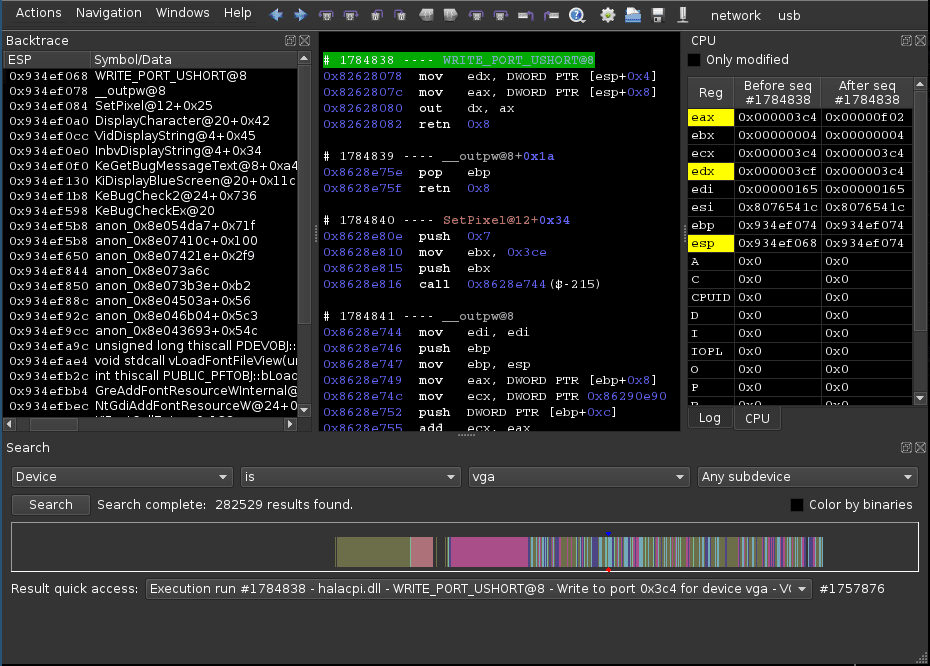
Searching accesses filtered by device is quite easy thanks to Axion. We only have to select a Device query and choose the vga device.

This returns all the memory/port accesses. Every colored bar shows either a memory access or a port access.

On the following screenshot, we selected a write to port 0x3c4 in the Search widget for the example. In the disassembler window, we can see out dx, ax and in the CPU widget we can see that ax = 0xf02 and dx = 0x3c4. So the value 0xf is written to the index 0x02 of the port 0x3c4. According to the previous link, this is the Map Mask Register.

Remember that REVEN Axion is timeless, meaning you can go back in the past of the execution. This will be really useful for the next part which consists in navigating through port accesses to find matches between the OSDev table and our case.
Finding the VGA mode
OSDev presents a [table][VGA_table] describing the values of relevant VGA registers according to their respective video mode. The first step is to find if the BSoD is using a text mode or a graphics mode.
Bit 0 of the [Attribute Mode Control register][attrreg] (port 0x3c0, index 0x10) determines whether the graphics mode is enabled. So, we queried for the VGA - 3c0 subdevice and looked at the results: the bit is set, we are in graphics mode.
We repeated this operation for the other registers in this table, and determined the BSoD is displayed using VGA mode 0x12 (640x480 planar 16-bit color).
Interpret accesses in order to recreate an image
Dump memory accesses
We’re going to dump all memory accesses between physical addresses 0xa0000 and 0xaffff (VGA VRAM) using this python code:
import reven
import struct

p = reven.Project("localhost", 13370)
t = p.traces()[0]

accesses = {}
for acc in t.search_memory_access(0xa0000, 0xffff):
	accesses[acc.point] = acc
accesses.sort(key=lambda tup:tup[0])
Generate image from VGA VRAM
We are now ready to generate the buffer:
buffer = [0] * 640 * 480
for p, acc in accesses:
	if not acc.is_write:
		continue
	offset = acc.physical_address & 0xffff
	buffer[offset] = acc.content
And then the black and white image:
rgb_array = [(0, 0, 0)] * 640 * 480
for x in range(640):
	for y in range(480):
		byte = buffer[y * 640 / 8 + x / 8]
		bit = 7 - x % 8
		color = (byte >> bit) & 1
		rgb_array[y * 640 + x] = (255 * color, 255 * color, 255 * color)

from PIL import Image
img = Image.new('RGB', (640, 480))
img.putdata(rgb_array)
img.save('out.png')
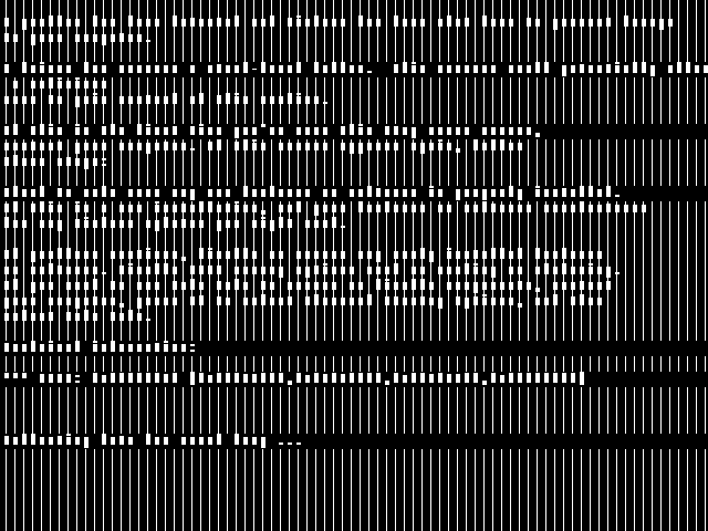
And that’s what we get:

It’s a little weird, right? Seems like we’re missing something.
How VGA mode 0x12 works
Write modes
There are 4 different write modes, however only mode 1 and 2 are of interest in our case so we will summarize how they work. See [this link][gfx_mode] for more detailed information about write modes.
In VGA you cannot write to the framebuffer directly, even in graphics mode. Mode 0x12 consists of four planes which each contain 1 bit of the 4-bit color index for a pixel. So if you, say, write an 8-bit value to plane 0 at position 0, you’re actually writing bit 0 of the first 8 pixels of the plane. But again, you can’t write to the planes directly: you’re actually writing a value to a logical address (0xA0000-0xAFFFF in our case) which triggers an MMIO access. This host value is passed to the hardware pipeline which will, according to various settings, transform this value and output it to the planes.
In write mode 1, the host data is not used by the pipeline. Instead, it will directly use the content of the latch, which is filled with the contents of the last read access. Since we don’t really need to emulate the latch for now, we will ignore all values if this mode is enabled. We didn’t in the previous script, which is why we can’t see horizontal lines sometimes.
In write mode 2, bits 0 to 3 of the data are duplicated across 8 bits of, respectively, planes 0 to 3. Then the [bit mask][bit_mask] is used to select which bits to keep.
Palette
The DAC [palette][colorreg] can contain up to 256 16-bit colors, which are indexed in the 16 [registers][palreg] of the attribute controller, which in turn are referenced by the 4-bit color index value stored for each pixel.
The advantage of this system is that you can change colors simply by changing attribute controller’s indexes, which avoids storing and redefining palette colors each time.
Reproducing accesses in a minimal kernel
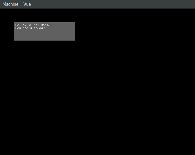
In order to check that we have found the right video mode (and also for the sheer fun of it), I developed a minimal kernel which displays colored pixels. Again, I took [this table][VGA_table] as an example and looked for the values written during the BSoD in Axion to reproduce the content of the registers.
I released the code of what I’ve done [here][vga_kernel_github] and it looks like this:

Using bit masks
Now that we know and understand the BSoD write modes, let’s get back to our script and try to reproduce the screen content correctly.
Actually, we need to get [bit masks][bit_mask] in order to render the text, because we’re in write mode 2 as I mentioned above. So we need to reproduce the same steps we did in Axion earlier, but this time with Python code:
bit_masks = {}
def found_data(point, mask, name, previous_data):
	global bit_masks
	if previous_data != mask:
		bit_masks[point] = mask
	return mask

def browse_ports(register_list, search_devices):
	for vga_register in register_list:
		vga_register += [False, None]

	for point in t.search_point([reven.DeviceCriterion("vga", dev) for dev in search_devices], None, None, False):
		point = point.next().next()
		cpu = point.cpu()
		for vga_register in register_list:
			(port, index, name, selected_index, previous_data) = vga_register

			# Get the index and port values, whether it's a single access or two
			if cpu['ecx'] & 0xffff == port:
				selected_index = False
				if cpu['eax'] & 0xff == index:
					selected_index = True
					if "ax" in str(point):
						previous_data = found_data(point, cpu['eax'] >> 8 & 0xff, name, previous_data)
			if cpu['ecx'] & 0xffff == port+1 and selected_index:
				previous_data = found_data(point, cpu['eax'] & 0xff, name, previous_data)

			vga_register[3] = selected_index
			vga_register[4] = previous_data

browse_ports([[0x3ce, 0x08, "0x3ce:8 Bit mask"]], ["VGA - 3c0"])
This script may look a tad complicated, but we’re simply extracting the actual VGA register values from the port accesses, and sorting them out by execution points.
Next, we will merge accesses and [bit masks][bit_mask] in a single array and sort them:
sorted_bit_masks = []
for p in sorted(bit_masks.keys()):
	sorted_bit_masks.append((p, bit_masks[p]))

sorted_accesses = []
for p in sorted(accesses.keys()):
	sorted_accesses.append((p, accesses[p]))

sorted_all = sorted_bit_masks + sorted_accesses
sorted_all.sort(key=lambda tup:tup[0])
To generate the buffer, we’ll need to apply the [bit mask][bit_mask] first, so our generation code becomes:
buffer = [0] * 640 * 480
current_mask = None
for p, acc in sorted_all:
	if type(acc) is int:
		current_mask = acc
		continue
	if not acc.is_write:
		continue
	offset = acc.physical_address & 0xffff
	if acc.content & 1:
		buffer[offset] |= current_mask
	else:
		buffer[offset] &= ~current_mask
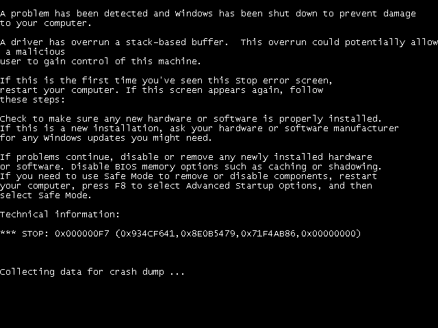
And finally, we can generate our image using the same code than above:

Now it’s perfect. We saw earlier that the data written in write mode 1 is ignored. If we take a look at the data written in this mode with Axion, we see that only zeroes are written, so we don’t need to take it into account.
Note that we didn’t care about the palette and planes 1 to 3 in this example.
Conclusion
We saw an example of reversing using Axion, then using the Python API. I made a widget for Axion using what we’ve done in this article, which is in the integration phase. It allows to see pixels displaying one by one with full palette handling.
I hope you enjoyed reading this, if you have any question feel free to post a comment.

